
Building the filter
The interface between the Arduino Uno and the audio amplifier (or PC)
Why do I need a filter?
You cannot connect digital outputs from the Arduino directly to an amplifier (or PC): besides getting awful sound quality, from no sound at all to a full-volume scream, it could damage the amplifier, the loudspeakers and/or your ears.
The filter converts digital (PWM) outputs from the Arduino into an analog audio signal suitable for an audio amplifier, mixes the six voices into a single channel and removes unwanted higher frequencies.
Using a breadboard
The easiest way to build the filter is with a "breadboard" where components can just be inserted without soldering. The same breadboard is a good place for the three control buttons, unless you plan to go by remote control only (via USB and serial terminal).
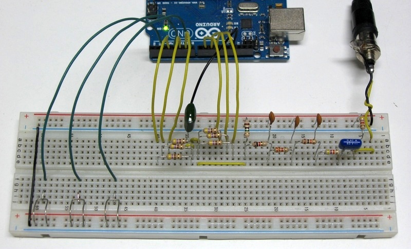
Before going into details, here is the actual filter I built on a breadboard:
Circuit diagram
If you are comfortable with electronics, here is the circuit schematic. Click on the image for the zoomable version in PDF format:
If you are less experienced, do not worry; just skip this image and read on.
Note that R12 may not be required; see Connecting to the amplifier (or PC) below.
Components you need
Component names (e.g. "R1") are those of the circuit diagram above; you do not need the names if you just follow the visual instructions below.
Resistors (1/4 W, 5% tolerance):
R1-R6  470 ohm   (yellow, violet, brown, gold)
R7     1 megaohm (brown, black, green, gold)
R8     1 kohm    (brown, black, red, gold)
R9     3.3 kohm  (orange, orange, red, gold)
R10    10 kohm   (brown, black, orange, gold)
R11    47 kohm   (yellow, violet, orange, gold)
R12    4.7 kohm  (yellow, violet, red, gold)
Capacitors (with most common markings indicated):
C1     100 nF    ("100n" or "104" or "0.1")
C2     10 nF     ("10n" or "103")
C3     3.3 nF    ("3.3n" or "3n3" or "332")
C4     1 nf      ("1n" or "102")
C5     470 nF    ("470n" or "474" or "0.47")
Buttons:
(all) SPST (normally open, closed only while pressed)
As you can see in the picture above, I made primitive buttons using stripped connection wire (note that the finger touches the ground side of the button, to prevent damage to Arduino ports in case of electrostatic discharge).
You will also need a female audio connector suited for your output cable; see Connecting to the amplifier (or PC) below.
Assembling the filter
The image shows the layout of the components on the breadboard. Click on the image for the zoomable version in PDF format.
Just for clarity, I used different wire colors to identify their function: black wires are connected to ground, orange wires (yellow in my photo above) carry signals, green wires are for the control buttons.
Do not forget the jumper wires (wires connecting two holes), especially the two very short orange wires near the top center that are easy to overlook.
The GND (ground) wire at the top center should be connected to the breadboard exactly where shown in the above layout, i.e. very near the 100 nF capacitor (C1), to minimize unwanted high frequency spurious signals.
Note that the top right resistor near "Out" (R12, 4.7 kohm) may not be required; see Connecting to the amplifier (or PC) below.
Connecting the Arduino Uno
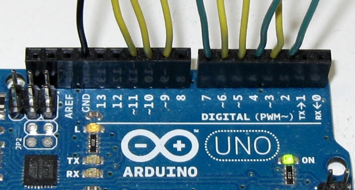
Before connecting the filter wires to the Arduino, be sure it is powered off: detach the USB connector and/or the power supply.
Numbered wires and the GND wire, at the top of the breadboard layout, must be inserted into the corresponding positions of the Arduino Uno "DIGITAL" connectors (e.g. the wire marked "5" goes into the socket position marked "~5").
Check and re-check
Wrong connections could potentially damage the Arduino, the amplifier, the loudspeakers and (if you are careless with the volume control) even your ears.
Double-check component values, jumpers and Arduino connecting wires (if you mix up wires of the same color when connecting to the Arduino, no damage is done).
Especially check the GND wire and the placement of the six 470-ohm resistors (R1-R6) and of the 100 nF capacitor (C1).
Connecting to the amplifier (or PC)
To connect the filter output to your amplifier input you have two options, depending on what you plan to use as amplifier:
In any case you will need a shielded audio cable. One end of this cable goes into the amplifier input plug; the other end goes into a female connector attached to the filter. I used an RCA connector (see the picture at the top of the page).
If you can use a soldering iron, the best solution is to solder two short wires to the female connector and insert them into the breadboard holes, as I did. If you do not have access to a soldering iron, or do not know how to use it, you could use a pair of cables with 'crocodile clips':
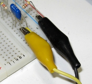
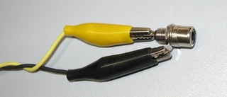
In that case twist the wires together for their whole length; this will reduce 'hum' (low frequency) noise and other possible problems due to the lack of shielding. Such problems will be worse if you are using a microphone input.
For the same reasons outlined before, check the GND connection (black) before turning on the amplifier. It must be solidly attached.
The filter is ready
Time to Compile the program and Play some music!
If you are experienced, you can of course go for a more permanent solution and solder the components on a pre-drilled prototype board, or even design an ad-hoc PCB (a 'shield' in Arduino jargon), using KiCad or similar CAD software for electronics, and contribute it to the project.
A note on 'ground loop' and other noise sources
If you hear high-pitched noise or intermittent noise from the amplifier or the computer, even when not playing, you probably have a ground loop problem, an annoying situation due to multiple ground returns. Two basic approaches to remove or reduce that noise are:
Some noise when using a computer microphone input is common, due to the cheap design and mostly unavoidable compromises of computer audio inputs.
Updated 23/10/16 by Enrico Colombini (erix@erix.it)